

Login
Please fill in your email address for download permission.
There is no account? Contact Us
 TOP
TOP

As the use of electrical medical equipment continues to expand, from hospitals and nursing homes to home monitoring and life support, more and more attention is paid to the safety of operators and patients. In terms of preventing dangerous or fatal electric shocks caused by line voltage, although medical equipment has strict design rules, good design practices and various safety standards, accidents may still occur. As long as the instrument fails, it will cause its housing or external probe to "live", so that the user or patient is in the ground path of the fault current. If the transformer is selected and placed properly, this situation can be avoided.
Of course, transformers have many uses, from step-up or step-down of alternating current (AC) voltage, or to disconnect the ground loop of sensitive sensor interfaces, to impedance matching, inter-stage coupling, and the conversion of single-ended and balanced circuits. They can also use a 1:1 turns ratio to provide electrical isolation between the AC line and the load. The importance and relevance of the last function in protecting operators and patients from medical equipment design failures is increasing.
This article will discuss the nature of possible failure modes and how to use transformers for AC line isolation to ensure the safety of line-powered medical instruments. Finally, we take the representative transformer of BEL Signal Transformer as an example to discuss some related standards and factors that must be considered to ensure that the transformer can provide the required isolation type and level. It will also consider its compatibility with modern assembly and production processes.
How did the electric shock happen?
To understand the risk of electric shock, we might return to the basic concept of electricity. If the current is driven by the AC line potential, flows through the human body and returns to the source, the user will be in danger. However, if the current does not have a return path, there will be no risk even if people touch the high-voltage line.
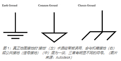
A single-phase AC line has three wires: live wire (L), neutral wire (N) and ground wire. The ground wire is a true ground connection and generally does not carry current. In standard house wiring, the ground wire is not insulated and is exposed. Unfortunately, the term "ground" is often misused in electronic circuit schematics and daily discussions. "Ground ground" is different from "chassis ground" or "common ground" (signal ground). The three have different symbols (Figure 1).
The role of the isolation transformer is to allow the AC voltage to reach the operating equipment and its circuit (load), while preventing the current from flowing through the user and returning to the neutral line. The reason why this does not happen is because the isolation transformer does not have a wire from the neutral line to the ground, so the current does not flow through the user. The isolation transformer can even use a 1:1 turns ratio, so that its input and output have the same voltage. In addition, there are some devices that can step down the secondary side voltage, which usually simplifies the conversion, rectification, and regulation of the circuit's power rail.
Electricity kills
People usually associate the risk of electric shock with a higher voltage. This is a valid association, but only indirect. Whether it is at the lethal level or below the lethal level, the cause of the electric shock is the current flowing through the body. The electric current enters and passes through the human body because of the pushing (forcing) of the voltage. This relationship can be clarified by the term "electric potential" (EMF), which was very common in the early years (and still in some cases).
It is important to keep in mind the basic principles of two circuits:
Voltage is not defined at a single point, but is defined and measured between two specific points. A more apt name than voltage is "potential difference."
The potential difference causes the flow of current. The magnitude of the current depends on the resistance between two points, which can be determined by Ohm's law. The greater the potential difference, the greater the current and the greater the risk.
So what are the risks of battery-powered equipment without an AC line connection? Even with high-voltage batteries, there is no danger of electric shock (unless the user grabs one end of a battery with one hand and the other end with the other). If the housing is connected to one of the battery terminals and thus to the user, there is still no current path from the user back to the other battery terminal.
There are also some line-powered power tools that do not have a safety ground, but do not use an isolation transformer: how is this possible? Until a few decades ago, construction tools such as drill bits used metal casings. If there is an internal fault, the housing will be "live", and the current path may flow through the user. In order to prevent this from happening, people will connect the metal shell to the ground terminal of the equipment's AC wire. However, this is always a dangerous solution, because in many practical cases, due to problems with wires and sockets, or the use of "fake" three-wire to two-wire adapters on ungrounded sockets, the grounding of the wires is not Will be really connected to ground.
The currently widely adopted solution is the "double insulation" design. The internal circuit of the tool is still insulated, the shell is not conductive, and there is no exposed conductive part. In this way, even if there is an internal failure and a short circuit in the shell, or the drill bit hits the live AC line on the wall, the user can be protected from the current. Double-insulated tools comply with the National Electrical Code (NEC) standards and are the first choice because they do not rely on the ground connection that often occurs in three-wire plugs. In fact, double insulated tools and instruments only have a two-wire plug for the live and neutral connections.
Even small currents are risky
The obvious question is: What is the maximum current level that is dangerous or fatal to human safety? There are multiple answers to this question, depending on which part of the human body the current acts on and what adverse effects it has on the human body.
Standard line voltage (110/230 volts; 50 or 60 hertz (Hz)) across the chest, even for a fraction of a second, with currents as low as 30 milliamps (mA), may induce ventricular fibrillation. Please note that at around 500 mA, the danger level of direct current is much higher, but this article only discusses alternating current and its isolation. If the current path passes directly through the heart, such as through cardiac catheters or other types of electrodes, even a much lower current of less than 1 mA (AC or DC) can cause heart tremor.
The following are some standard thresholds that are often quoted when describing the current flowing through the body through skin contact:
1 mA: almost imperceptible
16 mA: The maximum current that an ordinary person can grasp and "let go"
20 mA: Respiratory muscle paralysis
100 mA: ventricular fibrillation threshold
2 Ampere (A): Heart arrest and internal organ damage
The current level is also a function of the current path, that is, where the two points of contact with the body are, such as across or through the chest, from the arm down to the foot, or through the head.
The maximum safety limit is strict
The magnitude of the current is a function of skin resistance and body mass. The guidance provided by the National Institute of Occupational Safety and Health (NIOSH) states: “In dry conditions, the human body may provide resistance as high as 100,000 ohms (Ω). Wet or broken skin may reduce the human body’s resistance to 1000Ω. At the same time, high-voltage electrical energy quickly destroys the human skin and reduces the resistance of the human body to 500Ω." Ohm's law (I = V/R) quantifies the rest of the current situation.
Of course, the prudence of the margin of safety requires that the maximum allowable current is much lower than the quoted figure. This is a complex issue involving a series of overlapping standards, many of which have now been internationally "unified". These standards cover factors such as allowable leakage current, dielectric strength, creepage and gap size.
What is the difference between a medical equipment rated isolation transformer and a standard AC power transformer? After all, they all use the primary and secondary windings on the magnetic core to achieve 1:1 or other conversion ratios. The difference is that traditional transformers do not and do not need to meet all the above regulatory requirements, and the degree of strictness is much lower.
No single number can be assigned to each parameter, because their maximum value is a function of many factors. They are also defined based on whether the overall design uses single or dual protection (MOP), and whether the MOP is patient protection (MOPP) or operator protection (MOOP).
Among the many related standards, including:
IEC 60950-1:2001, "Information Technology Equipment-Safety-Part 1: General Requirements"
IEC 60601-1-11:2015, "Medical electrical equipment-Part 1-11: General requirements for basic safety and basic performance-Subsidiary standards: Requirements for medical electrical equipment and medical electrical systems used in home healthcare environments"
ISO 14971:2019, "Medical Equipment-Application of Risk Management in Medical Equipment"
The description of these standards and many of their terms and test conditions is far beyond the scope of this article. However, there are two project development strategies that will help accelerate designers to develop systems that meet the requirements of medical isolation regulations.
When cooperating with component manufacturers, the manufacturers should reliably prove that they have professional skills and capabilities, and can understand, implement and meet these requirements and many standards that define these requirements. Designers should not try to figure out all of this by themselves, because it will be very time consuming.
As part of the component strategy, individual components (such as transformers) that comply with relevant standards should be used whenever possible. The less attractive option is to design with non-standard components, and then add anything needed around them to comply with the standard, which is usually complicated and expensive.
These standards put forward various requirements on the performance of isolation transformers, which will eventually affect the entire product, such as:
Insulation class and high potential (withstand voltage) tests are used to characterize the insulation integrity and breakdown voltage within and between windings; usually in the range of several thousand volts.
The creepage distance (the shortest surface distance between two conductive parts) and the gap (the shortest distance through the air between two conductive parts) to avoid high-voltage arcing; these distances are specified as a function of the transformer rated voltage.
Leakage current refers to the leakage current from the winding to the core and from the winding to the winding when voltage is applied to the transformer; generally it must be less than 30 microamperes (µA).
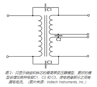
The leakage current caused by the intra-stage and inter-stage capacitance, which is a function of the transformer design, core and winding, must also be in the range of 30μA or less (Figure 2).
The flammability rating must comply with (but not limited to) UL 94V-0, and the burning time and afterfire time after repeated application of flame and dripping water shall be evaluated in the vertical burning test.
The test that meets the standard is carried out in accordance with the detailed conditions stipulated in the standard, usually at the same time or after the transformer is subjected to electrical pressure and thermal pressure at high voltage and high temperature, respectively, to evaluate the worst case and after the worst case occurs. Performance.
Existing isolation transformers have different functions
To better understand how isolation transformers solve the various needs of system designers, a good way is to look at some example models. Here we will focus on four representative units of Bel Signal Transformer, which have different features and functions, all for providing isolation, meeting regulatory requirements, and facilitating integration with assembly and production requirements.
1: M4L-1-3 is a 300 volt-ampere (VA) chassis mounting unit in the Signal Transformer More-4-Less series, with a rated dielectric strength of 4 kilovolts (kV) (Figure 3).
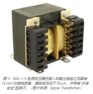
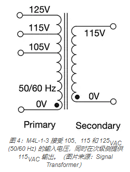
The multi-tap primary side of the M4L-1-3 can handle 105, 115, and 125 VAC (50/60 Hz) input voltages while providing 115VAC output voltage on the secondary side (Figure 4). Its design has a creepage distance of 12 mm between the input and output windings, and the leakage current is less than 30 µA. Physical connection considerations include IP20 type "touch-proof" terminals (not accessible by fingers and objects larger than 12mm), screws/binding clips for hard wiring, and 3/16" and 1/4" quick connections.
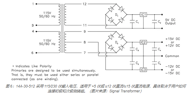
2: 14A-30-512 in the One-4-All series is a 30 VA, through-hole mounting unit with a rated dielectric withstand voltage of 4 kV (Figure 5).
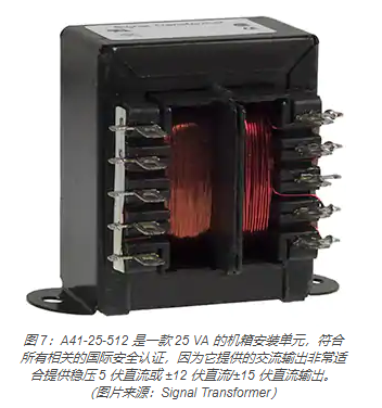
3: A41-25-512 is a 25 VA chassis-mounted device in the All-4-One series, with dual complementary outputs of 5VDC and ±12VDC/±15VDC regulated power supply (Figure 7). It complies with all relevant international safety certifications. Due to the dual primary side windings, the primary side working voltage can be 115/230 volts AC. It uses solder lugs/quick-connect terminals, and its leakage current complies with UL 60601-1 and IEC/EN 60601-1 requirements.
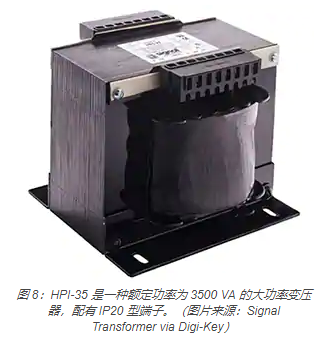
4: HPI-35 in the HPI series is a 3500 VA unit with a rated dielectric strength of 4 kV and a leakage current below 50 microamperes; it is equipped with IP20 type terminals (Figure 8)
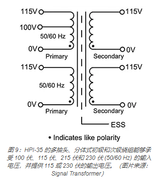
The HPI-35's multi-tap, split primary and secondary windings can withstand input voltages of 100 volts, 115 volts, 215 volts, and 230 volts (50/60 Hz), and provide 115 or 230 volt output voltages (Figure 9)
Conclusion
When using medical equipment, it is vital to protect operators and patients from injuries caused by occasional system failures and malfunctions and related electric shocks (usually fatal). As described in this article, isolation transformers provide this protection. They are suitable for AC line input voltage and can achieve the same output voltage with a 1:1 turns ratio, and can also achieve two-digit and one-digit output voltages through the secondary step-down winding. Its unique design and manufacturing process enable it to meet many strict safety regulatory requirements, such as rated dielectric voltage, leakage current, clearance and creepage, and flammability. Using these isolation transformers, designers can quickly get their final products to obtain regulatory approval and market.